The integration of optics in products has increased dramatically over the last decade. Smaller cameras, faster processors, and wireless connectivity have shown the world how amazingly small and connected digital imaging can be. Packaging all of this technology into such a small space can be challenging. Enter the Minnesota Design Center – A diverse team of 200 skilled engineers and technicians, with a common goal of developing manufacturable advanced technology products.
Designing the core of the optical system starts with simulation. Our optical engineers take the customer requirements and create a digital model of the complete optical chain. This can include custom and standard lenses, mirrors, lasers, LED’s, and other devices to direct and control the light. Once we have the system optimized to meet specification, we then import this optical model into SolidWorks 3D CAD software.
Our opto-mechanical design engineers carefully incorporate this optical system into the device design to ensure accurate alignment of all components. When adhesives are required, our process engineers work closely with the opto-mechanical team to select the best adhesives to enable quick curing, with minimal distortion, and maintain calibration throughout the operating temperature range of the device.
Accurate alignment of lenses with the imager chip can be critical. The Minnesota Design Center has expertise in developing robotic systems to actively align these components, and bond them in place with nanoliter-sized dispensing of the adhesive, along with LED flash curing to lock it into position. All of this work is done in our clean room environment to ensure there are no particles affecting the optical performance.
Careful design of test and measurement equipment is also required to gauge product performance. Our experienced test engineering team has the skills to architect custom systems that measure light output, dispersion patterns, wavelength, and many other parameters. We also recently added a metrology system that enables real time Modulation Transfer Function (MTF), Effective Focal Length (EFL) and distortion measurements of lenses so that we can be assured that our incoming lens components meet specifications.
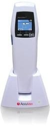
Some fun examples demonstrating these design capabilities include an ingestible Pill Cam, a hand-held vein viewer and even an advanced surveillance imaging system.
Pill Cam
Imaging of the small intestine can be difficult, as it is hard to access. Our customer had the idea of creating a pill cam that once swallowed, would take video images of the intestinal wall as it moved through the digestive tract. This posed many design challenges – how do you package all of these miniature components into a sealed device that is safe to swallow? We started by taking their hand built prototype and simplifying it to be more manufacturable. We redesigned the circuitry, going from discrete wires to a rigid flex design. We then developed an automated process to precisely align the lens to the imager, using a machine vision guided 4-axis robot. Our process engineers developed custom equipment to automatically fold up the camera/flex/battery assembly and insert it into the pill shell, then apply a very precise amount of adhesive, and attach the window cap to the device. Then to make sure we had a good seal, a custom leak test system was developed. Finally, a special washing process was developed to ensure a clean pill cam for the patient.
Vein Viewer
 Another customer came to us with a concept for an augmented reality vein viewer. Phlebotomists and other medical professionals often have difficulty locating a patient’s veins for needle sticks. Their concept was based on sensing the differences in light absorption between the skin and hemoglobin, and projecting light onto the skin to highlight vein location. They also wanted it to be as small as possible, so it could be portable. Our industrial design team worked closely with the customer, defining the usability profile of the device.
The optical team had some big challenges, such as which light wavelength to use, scanning method, lens system design, and overall optical engine development. All of this had to be in miniature form to meet the required usability plan. There were also thermal challenges to overcome, requiring tight collaboration with the mechanical and electrical engineers. This teamwork ultimately led to a highly successful, award-winning medical device.
Surveillance Imaging System
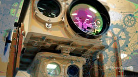
 While medical customers value our ability to fit electronics and optics into a small form factor, our surveillance customer needed advanced imaging over a distance of eight miles or more that could handle extreme weather and the vibration and G-forces of off-road driving. Working in conjunction with defense system integration experts at Benchmark Secure Technology in California, the opto-mechanical engineers implemented a design in which the cameras and optics were well supported in a lightweight housing that allowed both daylight and infrared cameras to operate perfectly in parallel. The entire design was modeled in CAD systems that revealed final weights and balances prior to cutting any metal in materials in order to meet ruggedization requirements and weight limitations.
As 5G and other technologies increase the amount of data that can easily be generated, transmitted and stored, barriers to working with the large amounts of data imaging generates are disappearing. We see new opportunities for digital imaging applications that let people see things and in places they couldn't before. Our team is ready to solving customers' big challenges using optics engineering to help people "see the light".
So, are the light bulbs (LED’s) going off in your mind? Want to talk to the Benchmark Minnesota Design Center about your next optical project? Email us at benchmark@bench.com or contact us here.
