Introduction
This case study focuses on the development of instrumentation for remotely sensing thermally generated electromagnetic radiation. Benchmark had the opportunity to design and manufacture a compact and rugged subsystem module for integration into a remote sensing device deployed in low Earth orbit (LEO) to take temperature measurements of the Earth’s atmosphere. The device integrates various subsystems to collect data valuable for improving weather models.
The Challenge: Crafting a Compact Satellite Payload System
Radiometers are a subcategory of pyrometers commonly used in the electromagnetic spectrum’s millimeter wave (mmWave) band. They receive electromagnetic radiation in thermal noise, filter it for a passband of interest, and, depending on the scientific need, either convert it to an intermediate frequency (IF) more favorable to signal processing or detect an entire channel with diode rectification. The collaboration described in this case study is for a radiometer operating in the V band between 50 and 58 GHz. Benchmark was responsible for developing an IF module to further channelize, amplify, and output the down-converted noise signal at both IF and baseband. The signal at baseband needed to be the rectified output of a traditional diode-detection circuit, proportional to the channel's input noise power. The most significant challenge was to engineer an instrument optimized for reduced size, weight, and power (SWaP) to facilitate better integration with LEO satellites to rival the performance of larger counterparts. It also required maintaining the instrument’s extended resilience to the harsh environmental conditions of orbit, often one of the most expensive aspects in developing technology targeted for space.
Benchmark’s IF module (IFM) would allow the customer to test and characterize the overall radiometer at the system level and its feasibility to interested parties. Operating as an independent internal research and development (IRAD) partner during the preliminary stages of development, Benchmark helped define the performance specifications for the IFM, balancing system-level specifications with constraints at the module level from component availability, manufacturing feasibility, and SWaP goals. Added to that list of challenges was the customer’s request for versatility. The IFM needed to allow for a level of compatibility with both the current and legacy superheterodyne front ends.
Benchmark's contribution included:
• Designing an IFM receiver compatible with legacy systems
• Defining performance specifications
• Specifying and procuring components
• Leveraging computer simulations to optimize the interaction of receiver components
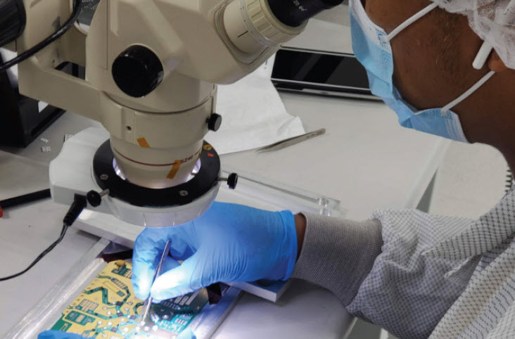
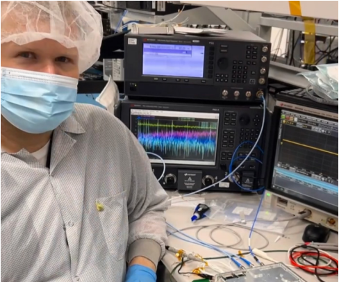
• Building prototypes for characterization
Background: The Principles of Radiometry
All matter emits electromagnetic radiation, with the quantity emitted directly correlating to the object’s temperature. Thermal cameras are based on this principle. What a thermal camera “sees” is the thermal energy of a hot object being emitted as electromagnetic radiation in the camera’s direction.
Even the radiation from very cold objects or objects at large distances can be measured with sufficiently sensitive equipment in a reasonably cold room. The detected radiation can be processed similarly to any other electrical signal with similar bandwidth, utilizing an antenna, an amplification stage, and back-end signal processing. The devices that detect and process electromagnetic radiation to measure temperature are called pyrometers. They measure temperature remotely and generally operate in an environment at a different temperature than the objects being measured. They are distinct from traditional thermometers that require direct contact with an object to take measurements. This discipline dedicated to detecting and measuring electromagnetic radiation from distant objects is termed “radiometry”, with the devices under scrutiny in this case study referred to as “radiometers.”
The Solution: IFM Receiver Development
The IFM solution included a channelized RF gain stage with a single broadband IF input amplified and distributed to multiple narrowband outputs. Two outputs were sub-band pass-through channels for spectral digital processing. The other channels were terminated with a classic diode detector circuit with video output, each generating a DC voltage signal with a magnitude proportional to the noise power contained in the channel’s passband. Benchmark's RF filter design team, Benchmark Lark Technology, designed and developed custom miniature surface mount technology (SMT) filters for each channel with significant out-of-band rejection to sample noise power accurately from only the sub-band of interest. Passband ripple was reduced by selecting amplifiers with low ripple and splitters with high output isolation to improve signal fidelity. The latter was essential to reduce reflected energy from adjacent channels intermixing with the noise signal in the channel of interest.
Benchmark was forward-looking in its component selection. Working closely with the customer, space-worthy versions of radiation-hardened components were identified, procured, and integrated into the prototype build. The extra cost was mitigated by the advantages of scheduling, eliminating the risk and additional design time inherent in using different components for prototype and flight-level designs. For example, component packaging for space-qualified components is typically larger than their commercial off-the-shelf (COTS) counterparts. It would require a redesign of the layout used in the prototype to accommodate their larger size.
The connectors for the project needed to operate in the designated frequency band with minimal insertion loss and hold up to the vibration, shock, and rigors of space exposure. Available COTS connectors were not readily available as connectors are not usually capable of surviving in space for extended periods. The dielectric or staking materials used in COTS connectors can result in outgassing and physical degradation from the vacuum of space. The outgassing of materials can change the size and shape of the components in the connectors and cause foreign object debris (FOD) that can obstruct mirrors or condense on optical components like solar cells and reduce power output. Physical failure can cause the dielectric and shielding to short out, resulting in complete system failure. The connectors were required to go through physical destructive analysis (PDA) to demonstrate flight readiness for space.
The sensitivity of the radiometer depended on contributions from each subsystem. Although gain stages in the RF chain prior to Benchmark's IFM module reduced the circuit's overall sensitivity to noise, it was still necessary to control the amount of noise and error that the circuit introduced. The IFM was designed with a sufficiently high signal-to-noise ratio (SNR) in its front-end circuitry to ensure that the noise signal from the atmosphere captured by the radiometer would be distinguishable from the noise generated by the components of the IFM. The error contributions of the operational amplifiers (op-amps) in the post-detection amplification stage were also significant contributors to the IFM’s usable dynamic range. Op-amps with sufficiently low error were chosen to extend that sensitivity range to as low of an output error level as possible. Often overlooked, external interference and signal integrity issues were significantly reduced by a well-designed return path for both the top-side metallic shielding interface and the internal connection through the PCB.
Due to the wide bandwidth of the IFM, computer-aided design (CAD) software was used extensively to simulate three-dimensional interaction between components and to optimize circuit geometries and PCB size. The deficient signal levels required conformal metallic shielding to minimize external and channel-to-channel interference, and simulations were performed to verify shielding effectiveness and the absence of cavity resonance. These predictions helped reduce the number of design iterations that would be needed and material waste. Automated design documentation facilitated rapid fabrication and assembly for prototype characterization and tuning to meet the tight schedule required by the customer. Integration of the IFM prototype in system-level testing has paved the road to space-grade radiometer development by integrating supporting hardware and software.
Summary of contributions from Benchmark:
• Designed an IFM receiver compatible with legacy systems
• Defined and developed the RF signal paths interconnecting the antenna to the receiver and other subsystems within the customer’s product
• Designed and developed amplification, channelization, detection, power and control circuitry, and implementation of space-approved parts and materials, including connectors for interfacing with other radiometer subsystems
• Specified printed-circuit-board (PCB) materials suitable for the space-based design
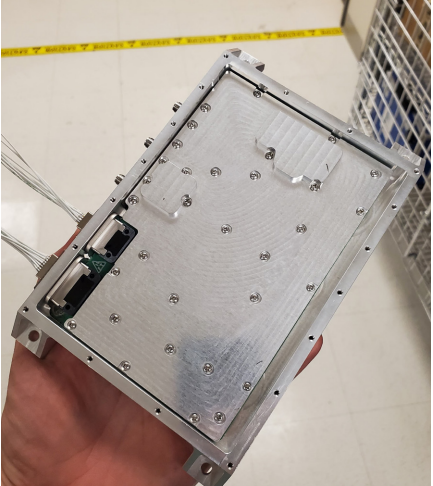
• Created layouts to miniaturize the physical size of the IFM receiver, detailing the precise placement of all components for board-level assembly and manufacturing
• Designed an RF chassis and shielding design (including outgassing-compatible gasketing) to provide the high isolation needed to protect weak signals from interference both internal and external to the IFM
The Results: Compact Microwave Sounder Unveiled
This collaborative project resulted in the development of a compact system designed for integration into small satellite radiometers and sounder instruments. Multiple systems in orbit provide enhanced backup data resources and extensive data coverage for weather modeling and prediction. The inclusion of Benchmark’s IFM digital receiver has significantly contributed to improved performance, system miniaturization, and the adaptability of the receiver to changing weather conditions.
Integration of an IFM receiver designed and developed with contributions by Benchmark improved performance and system miniaturization. This support provided flexibility of the receiver’s layout, allowing configuration of the channels at build time to collect the target sounding data. The channels are selected depending on the weather application of need.
About Benchmark
Benchmark provides comprehensive solutions across the entire product lifecycle, leading through its innovative technology and engineering design services, leveraging its optimized global supply chain and delivering world-class manufacturing services. The industries we serve include commercial aerospace, defense, advanced computing, next-generation telecommunications, complex industrials, medical, and semiconductor capital equipment.